Analysis of the Impact of RS485 Bus Topology on the Performance of Serial to Ethernet Converters
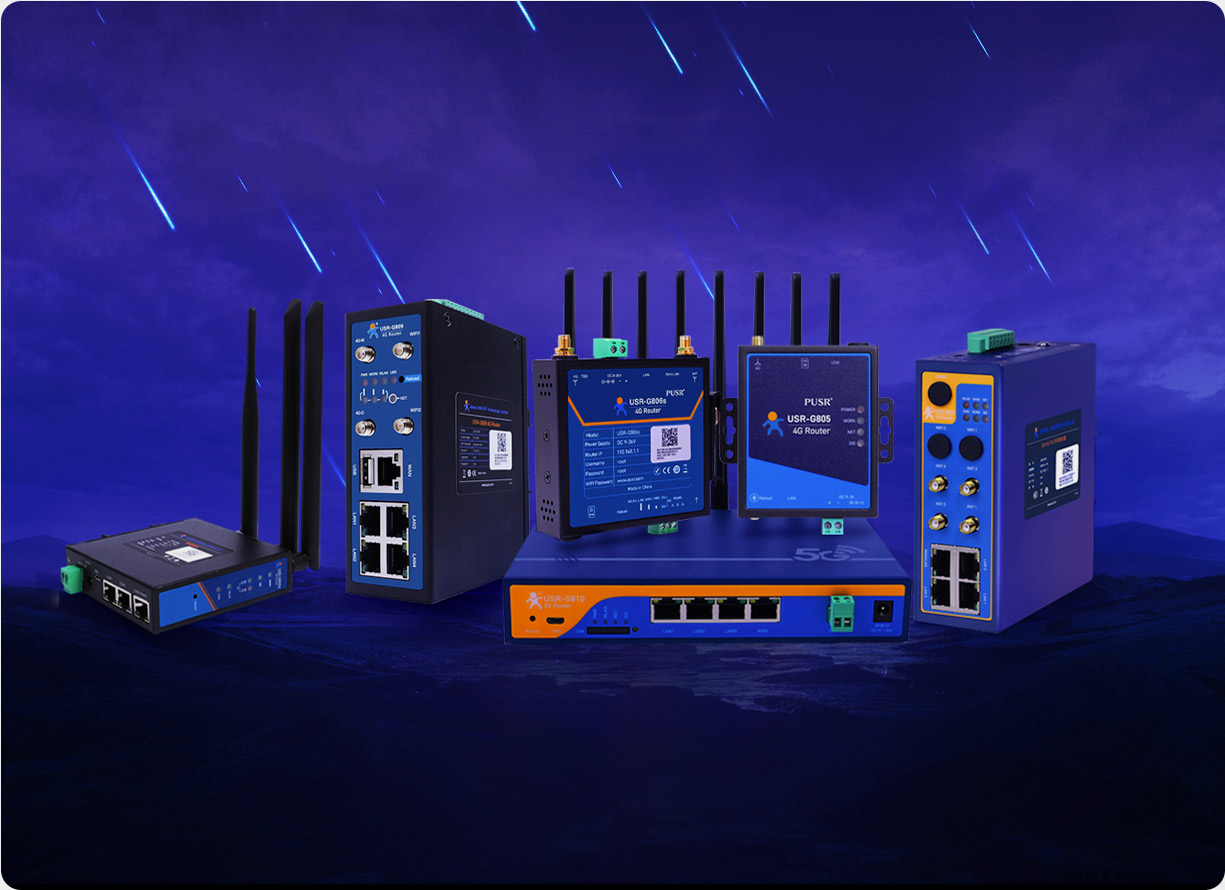
In the fields of Industrial Internet of Things (IIoT) and automation control, the RS485 bus has become the "gold standard" for device interconnection due to its characteristics such as long-distance transmission (1200 meters @ 9600 bps), strong anti-interference capability, and multi-node networking (up to 32/256 nodes). The serial to Ethernet converter, acting as the "interpreter" between RS485 devices and TCP/IP networks, directly influences the real-time performance, reliability, and system stability of data transmission. However, in practical applications, many engineers often overlook the potential impact of the RS485 bus topology (such as bus, star, and tree topologies) on the performance of serial to Ethernet converters, leading to issues such as communication delays, data loss, and even device disconnections. This article will delve into the impact of different topologies on the performance of serial to Ethernet converters, starting from the basic principles of topology, and considering key factors such as signal integrity, terminal matching, and node conflicts, while proposing optimization strategies.
The RS485 bus supports multiple topologies, but not all are suitable for industrial scenarios. Common topology types and their characteristics are as follows:
Structure: All nodes (devices) are connected in series through a main trunk line (twisted pair), with branch lines typically not exceeding 3 meters in length.
Advantages:
Low cost: Only a single main trunk line is required, making wiring simple;
High scalability: New nodes can be added by simply connecting them to the main trunk line without modifying the existing structure.
Limitations:
Risk of signal reflection: Long-distance transmission without proper terminal matching can easily cause signal ringing;
Single point of failure: A break in the main trunk line can lead to a complete network outage.
Applicable Scenarios: Linear device networking over short distances (<500 meters) with a relatively small number of nodes (<16), such as building temperature control systems.
Structure: All nodes are connected to a hub via independent branch lines, which in turn is connected to the serial to Ethernet converter.
Advantages:
Fault isolation: A failure in a single node does not affect other devices;
Easy maintenance: Adding or removing nodes does not require modifications to the main trunk line.
Limitations:
High cost: Requires a hub and more cables;
Signal attenuation: Excessively long branch lines (>10 meters) may cause signal distortion.
Applicable Scenarios: Scenarios with dispersed nodes requiring high reliability, such as laboratory equipment monitoring.
Structure: A hybrid of bus and star topologies, where the main trunk line branches into multiple sub-buses, each connecting multiple nodes.
Advantages:
Flexibility: Combines the scalability of bus topology with the fault isolation of star topology;
Wide coverage: Suitable for long-distance, multi-level networking (such as smart campus lighting control).
Limitations:
Complex design: Requires precise calculation of branch line lengths and impedance matching;
Conflict risk: Multi-level structures may exacerbate signal competition.
Applicable Scenarios: Large-scale, distributed industrial systems (such as oil pipeline monitoring networks).
The core performance indicators of serial to Ethernet converters include communication rate, real-time performance, stability, and anti-interference capability. Topology directly determines the performance of these indicators by influencing underlying factors such as signal integrity, terminal matching, and node conflicts.
RS485 signals are differential voltages (voltage difference between A/B lines), and their integrity is affected by the characteristic impedance of the transmission line (typically 120Ω) and terminal matching resistors.
Bus Topology:
Terminal matching: 120Ω terminal resistors must be connected at both ends of the main trunk line; otherwise, signal reflection at the ends can cause waveform distortion (as shown in Figure 1).
Branch line limitations: Excessively long branch lines introduce parasitic capacitance and inductance, slowing down the signal rise time and potentially triggering bit errors.
Case Study: A factory used a bus topology to connect 16 PLCs and experienced a bit error rate of up to 5% at 9600 bps due to the lack of terminal resistors; after adding terminal resistors, the bit error rate dropped to 0.01%.
Star Topology:
Hub design: Requires an active hub (Repeater Hub) to actively regenerate signals and avoid attenuation in branch lines;
Branch line length: If branch lines exceed 10 meters, small terminal resistors (such as 220Ω) should be added at the node end to reduce reflection.
Tree Topology:
Multi-level matching: Terminal matching is required at the end of each sub-bus, and impedance matchers (such as 120Ω parallel resistors) should be used at branch points.
RS485 is a half-duplex communication protocol, allowing only one node to send data at a time. Topology influences communication delay by affecting node competition and arbitration efficiency.
Bus Topology:
Conflict risk: When the number of nodes exceeds 32, the CSMA/CD (Carrier Sense Multiple Access/Collision Detection) mechanism may fail, leading to data collisions;
Delay optimization: Using a master-slave protocol (such as Modbus RTU) can reduce random competition, but a failure in the master node can cause a complete network outage.
Star Topology:
Conflict isolation: The hub can physically isolate node signals to avoid competition;
Increased delay: Signals need to be forwarded through the hub, adding approximately 50-100μs of delay per communication (depending on hub performance).
Tree Topology:
Hierarchical delay: Data needs to be uploaded level by level to the main trunk line, with delay proportional to the number of levels (e.g., delay in a 3-level tree topology may exceed 1ms);
Priority scheduling: Software-defined priorities (such as prioritizing emergency data) can be implemented, but require the serial to Ethernet converter to support QoS (Quality of Service) functionality.
Industrial environments are subject to strong electromagnetic interference (EMI), power supply noise, and other interference sources. Topology determines system anti-interference capability by influencing signal paths and grounding design.
Bus Topology:
Common-mode interference: If the main trunk line does not use shielded twisted pair (STP) or has poor grounding, common-mode voltages may exceed the ±7V threshold (RS485 standard), causing communication interruptions;
Ground loops: Ground potential differences between multiple nodes may form ground loop currents, burning out the interface chips of serial to Ethernet converters.
Star Topology:
Interference isolation: The hub can provide optical isolation (such as the USR-N520's 15kV electrostatic protection) to block ground loops;
Shielding requirements: Branch lines still require STP, and the hub housing must be reliably grounded.
Tree Topology:
Hierarchical grounding: The main trunk line and sub-buses require independent grounding to avoid interference coupling;
Redundancy design: Critical nodes can adopt dual-link backup (such as connecting to two sub-buses simultaneously) to improve fault tolerance.
To maximize the performance of serial to Ethernet converters, it is necessary to select appropriate hardware parameters and software functions based on the characteristics of the topology.
Bus Topology:
Interface protection: Choose a serial to Ethernet converter (such as the USR-N520) that supports ESD (electrostatic discharge) protection ≥15kV and EFT (electrical fast transient) protection ≥4kV;
Signal isolation: Prioritize magnetic or optocoupler isolation designs to block ground loops;
Terminal matching: Choose a converter with built-in terminal resistor switching functionality (such as the USR-N520, which can enable 120Ω terminal resistors via software).
Star Topology:
Hub compatibility: Ensure the serial to Ethernet converter supports hub power supply (PoE) or external power redundancy;
Low-delay design: Choose a converter with an RTOS (Real-Time Operating System) architecture to reduce hub forwarding delays.
Tree Topology:
Multi-port support: Choose a converter that supports more than 8 ports (such as the 8-port version of the USR-N520) to reduce hierarchy levels;
Wide temperature design: Adapt to outdoor environments (-40℃~85℃) to avoid signal distortion due to temperature drift.
Protocol Optimization:
Bus topology: Use the Modbus RTU master-slave protocol to reduce random competition;
Star/tree topology: Support industrial protocols such as MQTT or OPC UA to implement priority scheduling and data caching.
Fault Diagnosis:
Choose a converter that supports link status monitoring (such as the USR-N520's Web interface, which displays signal strength for each port in real-time) to quickly locate broken lines or interference sources;
Enable watchdog functionality to automatically restart crashed devices.
Security Mechanisms:
Configure IP/MAC address binding to prevent unauthorized node access;
Enable AES-128 encryption to avoid data eavesdropping or tampering.
Taking the USR-N520 serial to Ethernet converter as an example, it achieves optimized adaptation to multiple topologies through the following designs:
Hardware Redundancy:
8 RS485 interfaces, each independently isolated (15kV ESD protection), supporting mixed bus/star networking;
Built-in terminal resistor switching switches for one-click adaptation to bus topology.
Signal Optimization:
Adopts magnetic isolation technology to block ground loops;
Supports automatic signal flow control (RTS/CTS) to avoid data loss during high-speed communication (115200 bps).
Intelligent Management:
Web interface displays signal quality and communication rate for each port in real-time;
Supports both Modbus TCP and RTU protocols, compatible with bus master-slave architectures and star transparent transmission.
Implementation Effects:
In an automotive factory's assembly line (bus topology): The USR-N520 connected 32 PLCs and achieved a 0% bit error rate at 9600 bps by enabling terminal resistors and using the Modbus RTU protocol;
In a smart agricultural park (tree topology): The 8-port version of the USR-N520 directly connected to three levels of sub-buses, prioritizing irrigation control commands through QoS functionality with a delay of <200ms.
The topology of the RS485 bus is not a static choice but requires "co-design" with the hardware performance and software functions of serial to Ethernet converters. For example, bus topology relies on the terminal matching and anti-interference capabilities of serial to Ethernet converters; star topology requires low-delay forwarding and hub compatibility from serial to Ethernet converters. In the future, with the integration of TSN (Time-Sensitive Networking) and 5G technologies, RS485 buses will evolve towards "deterministic communication" and "high bandwidth," while serial to Ethernet converters will need to continuously innovate in topology awareness and adaptive matching.