Design of Solar-Powered Cellular Gateway: In-Depth Analysis of Battery Capacity Calculation and Charging Strategies
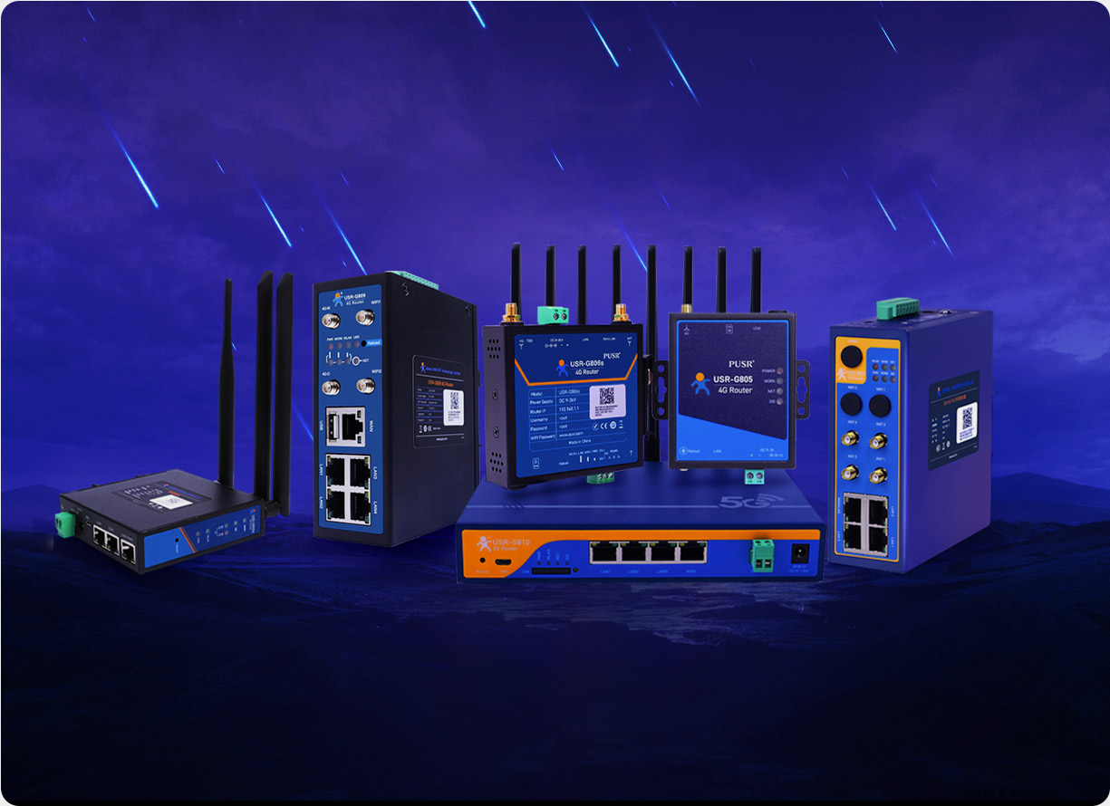
In the wave of the Industrial Internet of Things (IIIoT), the cellular gateway, as the core hub connecting field devices to cloud platforms, directly impacts the overall operational efficiency of the system with its stability and endurance. Particularly in remote areas or scenarios without stable power sources, solar-powered cellular gateway, with their clean and sustainable advantages, are gradually becoming the preferred solution for enterprises. However, how to scientifically calculate battery capacity and optimize charging strategies to ensure stable gateway operation in complex environments remains a core pain point for enterprises. This article provides systematic solutions for enterprises from two dimensions—battery capacity calculation and charging strategy optimization—combined with practical cases and theoretical models, and recommends a high-performance cellular gateway suitable for solar-powered scenarios: the USR-M300.
The calculation of battery capacity must comprehensively consider four core parameters: load power consumption, consecutive rainy days, safety factor, and depth of discharge (DOD). The basic formula is as follows:
Battery Capacity (Wh) = DOD × Daily Power Consumption (Wh) × Consecutive Rainy Days (N) × Safety Factor (Kb)
Daily Power Consumption: Determined by the load power (P) and the number of working hours per day (T), i.e., Daily Power Consumption = P × T. For example, if an industrial monitoring device has a power of 10W and operates for 8 hours per day, its daily power consumption is 80Wh.
Consecutive Rainy Days (N): Determined based on local meteorological data, typically using the historical longest consecutive rainy days. For example, southern regions can be designed for 5 days, while northern regions can be designed for 3 days.
Safety Factor (Kb): Compensates for factors such as battery aging and temperature effects, generally ranging from 1.2 to 1.5. For example, if a battery has been in use for 2 years, Kb can be set to 1.3.
Depth of Discharge (DOD): For lead-acid batteries, it is recommended not to exceed 80% (i.e., DOD = 0.8), while for lithium batteries, it can be relaxed to 90%.
A smart livestock farm needs to deploy solar-powered USR-M300 gateways to collect real-time data on temperature, humidity, and light, and upload it to the cloud via 4G. The design parameters are as follows:
Load Power Consumption: The USR-M300 gateway has a power consumption of 5W (standby) + 15W (peak data transmission). Assuming an average daily operation of 2 hours, the daily power consumption is approximately (5 × 24 + 15 × 2) / 24 ≈ 6.25Wh (simplified calculation; actual design should consider peak power consumption). More precise calculations should account for the data transmission frequency. Assuming data is uploaded every 10 minutes, with each transmission taking 30 seconds, the daily power consumption is 5 × 24 + 15 × (30 / 60) × (24 × 6) / 10 = 120 + 108 = 228Wh (this is a simplified example; actual adjustments should be made based on specific transmission protocols and frequencies). For simplicity, assume a daily power consumption of 100Wh (considering some redundancy).
Consecutive Rainy Days: The longest consecutive rainy days in the area are 3 days.
Safety Factor: Set to 1.3.
Depth of Discharge: Lead-acid battery, DOD = 0.8.
Substituting into the formula to calculate battery capacity:
Battery Capacity = 0.8 × 100 × 3 × 1.3 = 487.5Wh
If a 12V lead-acid battery is selected, the capacity required is approximately 487.5 / 12 ≈ 40.6Ah, which can be configured as two 20Ah batteries in parallel.
In extreme weather conditions, consecutive rainy days may exceed the design value. At this point, battery life can be extended by dynamically adjusting load power consumption:
Data Compression and Batch Reporting: The USR-M300 supports data compression algorithms, which can reduce the amount of data reported in a single transmission by 60%. Additionally, adopting a batch reporting mode can reduce the number of daily reports from 24 to 12, lowering transmission power consumption.
Edge Computing for Local Processing: Through the edge computing capabilities of the USR-M300, data preprocessing (such as threshold filtering and anomaly detection) can be completed locally, with only critical data uploaded to the cloud, reducing invalid transmissions.
Traditional solar charging controllers use PWM (Pulse Width Modulation) technology, which has a charging efficiency of only 60%-70%, especially lower under weak light conditions. In contrast, MPPT (Maximum Power Point Tracking) technology dynamically adjusts voltage and current to keep the photovoltaic panel operating at its maximum power point, increasing efficiency to over 90%. For example:
Weak Light Scenarios: In the early morning or on cloudy days, with a light intensity of 500W/m², an MPPT controller can capture 20%-30% more energy than a PWM controller.
Partially Shaded Scenarios: When a photovoltaic panel is partially shaded by leaves or dust, an MPPT controller can automatically adjust the operating point to avoid an overall efficiency drop due to local shadows.
The USR-M300 supports external MPPT charging controllers (such as the BQ24650 chip solution), enabling seamless integration with solar panels for efficient charging.
The charging process of lead-acid batteries should follow a "constant current-constant voltage-float charge" three-stage curve to avoid overcharging or undercharging:
Constant Current Stage: Charges rapidly at the maximum allowable current (e.g., 0.3C) until the battery voltage reaches the float charge voltage (e.g., 14.4V).
Constant Voltage Stage: Maintains a constant voltage while the current gradually decreases until the current drops below 0.05C.
Float Charge Stage: Maintains the battery in a fully charged state with a small current (e.g., 0.02C) to compensate for self-discharge losses.
The USR-M300 can achieve hardware-level three-stage charging protection through an integrated charging management chip (such as the DW01 + FS8205A combination), while also supporting software configuration of charging parameters to adapt to different types of batteries (e.g., lead-acid, lithium).
When light intensity is insufficient, the USR-M300 can automatically switch to a low-power mode:
Disabling Non-Core Functions: Such as turning off the Wi-Fi module and reducing CPU frequency.
Adjusting Data Reporting Frequency: Changing from real-time reporting to scheduled reporting (e.g., once every 30 minutes).
Enabling Local Storage: Temporarily storing data in local Flash memory during network disconnections or low battery levels, and uploading it later when light intensity recovers.
The USR-M300 is a high-performance, scalable comprehensive edge gateway designed to deeply meet the needs of solar-powered scenarios:
Ultra-Low Power Consumption: Equipped with a 1.2GHz dual-core CPU, it has a standby power consumption of only 0.5W and a peak power consumption not exceeding 15W, significantly reducing the load pressure on solar systems.
Multi-Network Support: Supports 4G + Ethernet dual-link parallel operation, with automatic switching in case of network failures to ensure uninterrupted data transmission.
Edge Computing Capabilities: Built-in with 2000 acquisition points, it supports data preprocessing and local closed-loop control, reducing cloud transmission volume.
Wide Temperature Design: Operates in a temperature range of -25°C to 75°C, adapting to extreme environments.
Modular Expansion: Supports the connection of 6 expansion units, allowing flexible matching of the number of DI/DO/AI/AO ports to meet diverse scenario needs.
Case Application: A remote oil and gas pipeline monitoring project adopted the USR-M300 + solar power solution. Through MPPT charging and dynamic power management, it maintained normal data uploads during 7 consecutive days of rainy weather, reducing annual maintenance costs by 80%.
With the advancement of the "dual carbon" goals, solar-powered cellular gateways will become the mainstream solution for the Industrial Internet of Things. Enterprises need to systematically plan from three aspects—battery capacity calculation, charging strategy optimization, and gateway selection—to achieve cost reduction and efficiency improvement. The USR-M300 provides enterprises with a one-stop solution with its low power consumption, high reliability, and flexible scalability. Click the button to have a one-on-one conversation with PUSR experts, obtain customized solar-powered cellular gateway design services, and embark on a new chapter of green smart manufacturing!