At present, the monitoring, operation, and maintenance of distributed photovoltaic grid-connection cabinets and secondary equipment in substations have long suffered from four typical pain points, which directly affect the stability of power grid operation and the efficiency of maintenance work.
The first is insufficient data transmission stability. A large number of early grid-connection cabinets still rely on 2G networks for data backhaul. As domestic 2G networks are gradually being decommissioned, equipment frequently experiences offline and disconnection issues. In some remote suburban and mountainous PV sites, data loss has even occurred for multiple consecutive days, leaving maintenance personnel unable to monitor the operational status of the grid-connection cabinets in real time.
The second is high manual inspection costs and significant risks of misoperation. Traditional secondary equipment in substations—such as pressure plates, air switches, and switching handles—cannot support remote control. Maintenance personnel must perform manual operations on-site, which not only results in low inspection efficiency but also carries the risk of human-induced misoperation, severely hindering the implementation of one-key sequence control operation modes.
The third is poor equipment reliability in harsh environments. Outdoor grid-connection cabinets operate over a wide temperature range from -25°C to 75°C. Some industrial-grade communication equipment lacks adequate protection, making them highly susceptible to downtime caused by electrostatic discharge, surges, and pulse interference. When faults occur at a site, alarm information cannot be uploaded promptly, causing missed optimal response windows.
The fourth is the difficulty in ensuring security and regulatory compliance. Power monitoring systems impose stringent requirements for identity authentication and encrypted transmission of data. Many general-purpose communication products fail to meet the relevant requirements of the "Regulations on Security Protection for Power Monitoring Systems," posing risks of data leakage and unauthorized access, and thus cannot pass the security compliance acceptance checks on the grid side.
This solution is built on the core logic of "panoramic perception – reliable transmission – intelligent control," establishing a three-tier closed-loop monitoring system that fully covers the monitoring needs of substations and grid-connection cabinets.
The first tier is the on-site perception layer. In the grid-connection cabinet, power quality monitoring devices, microprocessor-based protection units, and loop status sensors are deployed to collect full-scale operational data in real time, including voltage, current, power, temperature and humidity, switch status, and fault alarms. At the same time, electric actuators are installed on the pressure plates and air switches of secondary equipment to enable remote electric remote control, replacing the traditional manual on-site operation mode.
The second tier is the reliable transmission layer. While strictly adhering to the security zoning specifications of power monitoring systems, the collected data from serial devices inside the grid-connection cabinet is transmitted bidirectionally through industrial-grade cellular router equipment. All uplink data, after being encrypted and authenticated, is uploaded to the power monitoring platform via the secure access zone. This not only meets the wireless networking needs of remote sites but also fully complies with the security protection requirements of the production control zone.
The third tier is the platform management and control layer. A secondary intelligent monitoring system is deployed to realize five core functions: panoramic status monitoring of secondary equipment, remote control, automated routine inspection, secondary anti-misoperation verification, and online analysis of operational data. Building on primary anti-misoperation verification, secondary anti-misoperation logic is extended to enable integrated verification of primary and secondary equipment, fundamentally preventing misoperations and fully supporting the effective implementation of one-key sequence control operations.
To ensure the stable and compliant operation of the solution, the deployment process must strictly enforce four control requirements:
The first is compliant deployment of security zones. In the production control zone, products with general-purpose wireless communication functions are prohibited. All wireless transmission terminals must be deployed within the secure access zone. Communication between the communication proxy module and the terminal must be fully encrypted and authenticated. No critical business data shall be stored within the secure access zone. Transverse isolation devices must be deployed at zone boundaries, and no cross-zone general-purpose network services are permitted to traverse.
The second is standardized hardware installation. The cellular router device is mounted on an available DIN rail inside the grid-connection cabinet using standard DIN-rail clips. Power is supplied via a wide-voltage DC terminal block with direct wiring; external power adapters are prohibited. The device must be powered off before installing antennas. After connecting the RF ports to the corresponding antennas, unused RF ports must be fitted with matching loads. All RF connectors must be tightly wrapped with two layers of insulating tape and waterproof tape. The antenna ground must be equipotentially bonded with the grid-connection cabinet to prevent surge damage to the equipment.
The third is cabling and interference mitigation. Shielded RS485/RS232 dedicated cables must be used for serial communication lines. Cabling must maintain a minimum clearance of 15 cm from high-voltage power circuits to avoid electromagnetic interference from power cables. If 5GE data rates are used, shielded CAT6A cables conforming to the 802.3bz standard must be employed; unshielded CAT5E cables are prohibited to prevent persistent packet loss caused by external crosstalk.
The fourth is a closed-loop commissioning and acceptance process. After power-on, the network signal strength must first be verified via signal status indicators. Serial pass-through testing, connectivity testing of four independent Socket links, and verification of registration packets and heartbeat packet configurations must be completed sequentially. Finally, end-to-end identity authentication for encrypted communication must be validated. Only after all test items pass may the equipment be connected to the power monitoring platform. Deployment and commissioning records must be retained for subsequent compliance acceptance.
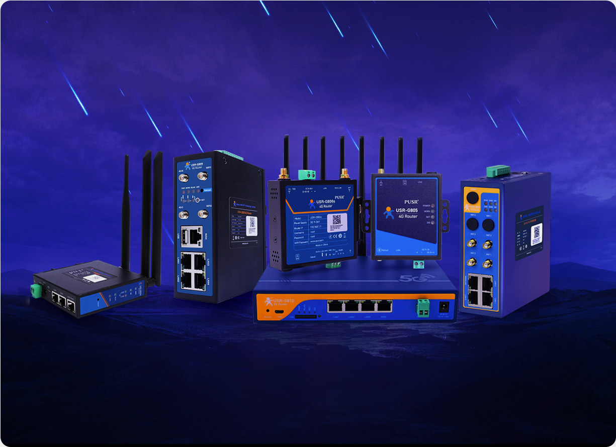
The PUSR USR-G771 LTE Cat-1 cellular router selected for this solution is fully adapted to the monitoring scenarios of substations and grid-connection cabinets, with prominent core advantages.
This product supports Cat-1 network access from the three major telecom operators while also being compatible with China Mobile and China Unicom 2G networks. During the transitional phase of 2G decommissioning, it ensures smooth network switching, thoroughly resolving the disconnection issues of traditional 2G cellular routers.
The product adopts industrial-grade design standards, with an operating temperature range covering the extreme limits of -25°C to 75°C. It supports Level 3 ESD protection, Level 3 surge immunity, and Level 3 EFT pulse immunity. With a built-in independent hardware watchdog, it can operate stably for extended periods under harsh outdoor conditions.
The device comes with both RS232 and RS485 standard terminal interfaces, making it compatible with most relay protection and power quality monitoring devices inside grid-connection cabinets. It supports four independent Socket connections, enabling simultaneous data upload to multiple platforms.
The product supports three configuration methods—serial port, network, and SMS AT commands—and is accompanied by a PC-based visual configuration tool, greatly improving on-site commissioning efficiency. It also supports FOTA differential remote upgrades, with small upgrade packages and low data consumption, allowing firmware updates without affecting ongoing on-site operations, ensuring long-term functional reliability of the equipment.
The built-in signal status indicators enable construction personnel to visually check signal strength and network type without connecting to a computer, significantly reducing the commissioning difficulty at outdoor sites. The integrated standard DIN-rail clips allow direct mounting onto standard DIN rails in grid-connection cabinets without additional drilling for fixation, greatly enhancing deployment convenience.
At present, the G771 has been widely applied in industrial scenarios such as remote networked alarms, agricultural environmental monitoring, and charging pile data transmission, fully meeting the core requirements of substation and grid-connection cabinet monitoring for high reliability, ease of deployment, and regulatory compliance.