Weak Wireless Signal from Cellular Router? A Comprehensive Guide to Gain Antenna Selection and Installation Angle Calculation
In Industrial Internet of Things (IIoT) scenarios, the stability of wireless signals directly determines the reliability of device communication. A car manufacturing enterprise once experienced a collective offline status of 200 PLC devices due to weak wireless signals, resulting in a production line shutdown for 4 hours and direct losses exceeding RMB 5 million. In a smart warehousing project, signal interruptions in AGV trolleys caused chaos in cargo handling, leading to a 300% surge in manual intervention costs. Behind these cases lies a critical issue: the optimization of gain antenna selection and installation angles for cellular router is the core solution to addressing weak wireless signals. This article provides enterprises with actionable solutions from three dimensions: antenna selection logic, installation angle calculation methods, and real-world scenario validation.
Industrial sites often contain obstacles such as metal cabinets, large equipment, and concrete walls, which cause significant attenuation of signals in the 2.4GHz/5GHz frequency bands. For example, a 10cm-thick concrete wall can attenuate 2.4GHz signals by 10-15dB, while metal cabinets may even completely block the signal.
Ordinary routers often use 3-5dBi gain antennas, whose signal coverage is distributed in a "doughnut" shape—wide vertical coverage but narrow horizontal coverage. In industrial scenarios, this design can easily lead to:
Insufficient long-distance transmission: The signal strength of a 3dBi antenna at a distance of 100 meters is 12dB lower than that of a 7dBi antenna.
Coverage blind spots: Low-gain antennas are prone to creating signal dead zones in multi-story factories or three-dimensional warehouses.
The antenna angle directly affects signal radiation efficiency. Experimental data shows:
90-degree vertical installation: The signal strength is 14dB higher than that of 0-degree horizontal installation (tested with an ASUS RT-AC68U as an example).
45-degree tilted installation: The signal strength is between the two above, but stability decreases by 20%.
Omnidirectional Antennas:
Applicable Scenarios: Point-to-multipoint communication (e.g., multiple devices in a workshop connecting to the same router), continuous coverage for mobile devices (AGV trolleys, inspection robots).
Typical Parameters: Gain of 5-7dBi, horizontal coverage of 360°, vertical beamwidth of 60-90°.
Case: An electronics factory adopted a 7dBi omnidirectional antenna, achieving a signal strength of -65dBm within a 200-meter radius, meeting PLC communication requirements.
Directional Antennas:
Applicable Scenarios: Point-to-point long-distance transmission (e.g., cross-workshop communication), directional signal enhancement (e.g., coverage of high-rise shelves in warehouses).
Typical Parameters: Gain of 10-16dBi, horizontal coverage of 30-120°, vertical beamwidth of 15-30°.
Case: A logistics center used a 12dBi directional antenna to achieve a signal strength of -70dBm at a distance of 1 kilometer, supporting the operation of an automatic sorting system.
The relationship between gain (dBi) and signal transmission distance can be approximately estimated using the formula:
Distance Gain = 10 × log10(Gain Value)
For example, upgrading the antenna from 3dBi to 7dBi can theoretically increase the transmission distance by approximately 3.7 times (10 × log10(7/3) ≈ 3.7). However, it should be noted that:
The cost of high gain: The vertical beamwidth of a 7dBi antenna is 30% narrower than that of a 3dBi antenna, requiring adjustment of the installation angle for compensation.
Real-world scenario correction: In environments with obstacles, it is recommended to reserve 20-30% gain redundancy.
Key Indicators: The VSWR should be ≤1.5, and the return loss should be ≥14dB; otherwise, signal reflection will cause power loss.
Testing Method: Use a network analyzer to measure the S11 parameter (input reflection coefficient) to ensure it is ≤-6dB.
Case: A steel enterprise experienced a 10dB drop in signal strength due to impedance mismatch between the antenna and the router. The problem was resolved after replacing the antenna with a matched one.
The signal radiation of an antenna can be simplified into a "doughnut" model:
Horizontal Coverage: Determined by the antenna gain; high-gain antennas provide longer horizontal coverage but narrower angles.
Vertical Coverage: Determined by the installation angle; the vertical beam is most concentrated when installed vertically at 90 degrees.
Fixed Devices: Measure the straight-line distance (L) and height difference (H) between the device and the router.
Mobile Devices: Plan the mobile path and determine the location of the weakest signal point.
Formula:
θ = arctan(H/L)
where θ is the angle between the antenna and the horizontal plane.
Case: If the height difference H = 3 meters and the distance L = 10 meters, then θ ≈ 16.7°, meaning the antenna needs to be installed at a tilt of 16.7 degrees.
Tools: Use a WiFi analyzer (e.g., "Wifi Analyzer" on Android) to measure the signal strength (RSSI).
Standards:
Static Devices: RSSI ≥ -70dBm.
Mobile Devices: RSSI fluctuation range ≤ 10dB.
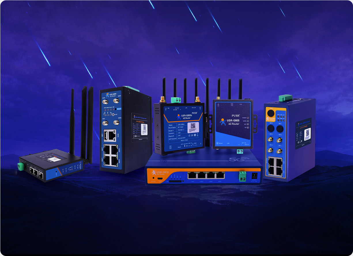
In response to the complex requirements of industrial scenarios, the USR-G816 5G cellular router provides an all-in-one solution:
Standard Configuration: Built-in dual-band WiFi antennas (2.4GHz/5GHz) with a gain of 5dBi, supporting 360° horizontal coverage.
Optional Upgrade: External 12dBi directional antenna for 1-kilometer long-distance transmission, meeting cross-workshop communication needs.
Multi-Band Support: Simultaneously supports 2.4GHz (wide coverage) and 5GHz (high speed), automatically switching based on device location.
Beamforming: Dynamically adjusts the signal direction to focus on the target device, improving signal strength by 10-15dB.
Installation Methods: Supports DIN rail, wall-mounted, and desktop installations to accommodate different space requirements.
Protection Level: IP30 protection (standard version), with an optional IP65 waterproof version for harsh outdoor environments.
Case Study of a Smart Factory:
Scenario: A 10,000㎡ factory with obstacles such as metal cabinets and concrete walls.
Solution: Deployed USR-G816 + 12dBi directional antennas, covering a radius of 500 meters with a signal strength of -68dBm.
Effect: The number of communication interruptions in AGV trolleys decreased from 5 times per day to 0, reducing maintenance costs by 70%.
If you are facing issues such as weak industrial wireless signals, numerous coverage blind spots, and frequent device disconnections, the USR-G816 5G cellular router can provide:
Free Signal Simulation: Simulate antenna selection and installation effects based on your factory layout.
On-Site Testing Service: Provide sample machines for real-world scenario testing to verify signal strength and stability.
Contact us to obtain a customized solution and bid farewell to the era of weak industrial communication signals!